Director's Corner
2 October 2008
 Barry Barish |
Achieving tiny beam spot sizes with ATF2
The ILC's beams pass through each accelerating element once before they are directed to collide with the beam travelling in the opposite direction. This poses the two main challenges in the ILC: to achieve a very high gradient in the accelerator in order to make it as short as possible while achieving the desired energy, and to achieve very small beam spots to maximise the probability of collisions by the crossing beams. The process of creating small beam spots relies on creating low-emittance beams, preserving the emittance during acceleration and transport, and focusing the beams to nanometres just before collision. Last month I had the opportunity to visit the Accelerator Test Facility (ATF) at KEK which creates small emittance beams that will be injected into ATF2, a final-focus beamline that will test the ability to bring the beam to the nanometre-scale beam spot sizes needed for the ILC.
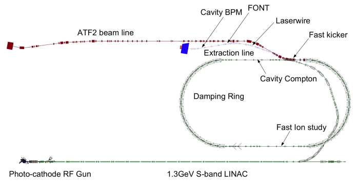 The layout for the ATF and ATF-2 at KEK The layout for the ATF and ATF-2 at KEK |
 Junji Urakawa of KEK and ATF/ATF2 Project Leader gave the GDE Executive Committee a tour of the facility Junji Urakawa of KEK and ATF/ATF2 Project Leader gave the GDE Executive Committee a tour of the facility |
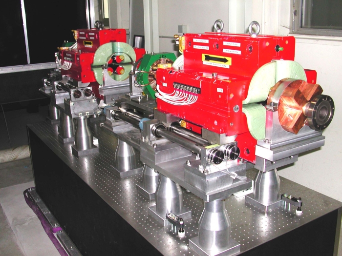 Final ATF2 doublet system contributed by the Laboratoire d'Annecy-le-Vieux de Physique des Particules (LAPP) in France Final ATF2 doublet system contributed by the Laboratoire d'Annecy-le-Vieux de Physique des Particules (LAPP) in France |
ATF2 exploits and builds on the successful Accelerator Test Facility at the KEK Laboratory in Japan. ATF was designed to achieve ILC-like low-emittance beams. The emittance, transverse components of the beam or its 'halo', should be less than two picometres at the nominal ILC bunch charge. The ATF beam begins from a photocathode radiofrequency gun that creates electrons that are then injected into a 1.5-GeV electron linac. The linac injects its beam into a 1.5-GeV circular damping ring designed to reduce the emittance by radiation damping. In order to achieve the desired low emittance, a high-resolution beam position monitoring system is being employed; both a broadband turn-by-turn mode with less than 10 micron resolution and a narrow band mode with high resolution in the range of about 100 nanometres. The low-emittance beam generated by the damping ring is extracted by a fast kicker magnet into the ATF2 beamline.
The purpose of ATF2 is to build and operate a test facility for developing and testing the challenging final focus for the ILC. One of our prime goals during the present phase of our work, Technical Design Phase 1, is to achieve a spot size of about 50 nanometres by 2010. The programme to demonstrate this is now getting underway with first tests to begin later this year. The ATF2 collaboration is highly international with components and testing being shared by a team from around the world and an organisation that is a mini-version of the global organisation required for the ILC.
Even during a period like this year, when we have had major funding problems in the US and the UK, the stability and progress of the overall ILC R&D programme has been in no small part due to the fact that so much of the important elements of our programme are built around existing large-scale test facilities. The ATF/ATF2 facility at KEK represents an important major investment by KEK and the international community in developing facilities for testing advanced accelerator concepts. This project is a very good model in many ways: it involves significant contributions from a widespread international collaboration; it has an organisational structure that shares responsibility and is a realistic test for having such collaborations; it is technically unique in enabling sophisticated tests like the ones for ILC; and last but definitely not least, it is an important laboratory and training ground for students.
We look forward to soon being able to use ATF/ATF2 for our very important studies of final focus design issues for the ILC.
-- Barry Barish