Director's Corner
23 July 2009
 Barry Barish |
Accelerator Design and Integration: Considerations for distributing high-level RF power for a single tunnel configuration
The main thrust of our ILC accelerator design work during the Technical Design Phase (TDP-1 and TDP-2) is to refine the design presented in the Reference Design Report (RDR) towards a more coherent concept, and one that is better optimised for performance to cost to risk. Our approach is to study a set of carefully chosen potential changes to the RDR baseline aimed at producing a new baseline next year as the final milestone in TPD-1. The new baseline will then become the basis of the technical design (TPD-2) that will be completed and documented by the end of 2012. One of the most complex and difficult changes under consideration is changing from the RDR’s double-tunnel to a single-tunnel configuration. A key problem to solve for a single-tunnel configuration is how to deliver the high-level radiofrequency power (HLRF) to the cryomodules. There are two very different solutions being proposed, and the choice between them may be site dependent.
 The ILC Reference Design uses a double-tunnel configuration with the klystron high-level RF system in an accessible service tunnel. The ILC Reference Design uses a double-tunnel configuration with the klystron high-level RF system in an accessible service tunnel. |
A primary motivation in considering a single underground tunnel for the main linac and associated beamlines is the potential large cost savings realised by eliminating an entire 30-kilometre-long underground tunnel. However, removal of the second (service) tunnel requires us to revisit the original reasons we chose a double-tunnel solution for the RDR: concerns about availability and safety.
The double-tunnel configuration provided us with a conservative solution for the RDR, since access to klystrons, modulators, electronics and other hardware during beam operation improves availability, and escape routes from one tunnel provide straight-forward safety solutions. Nevertheless, the potential savings for a single-tunnel configuration could be more than 100 million dollars, even including anticipated extra costs to achieve good availability and safety solutions. For this reason, we have always planned to come back to study the single-tunnel configurations. One of the primary goals of the present study is to quantify the potential savings and to present realistic concepts for single-tunnel configurations.
Safety is a difficult issue to plan for without a specific site to know local conditions and safety rules, since an acceptable safety scheme may differ for different sites. We are therefore carrying out studies to determine single-tunnel safety solutions for our full range of potential sites. If we adopt a single-tunnel baseline for the TDP-2, we must recognise that the final tunnel configuration will depend on the chosen site and the preference of the host country. The Technical Design Report (TDR) information, along with the RDR double tunnel study, will enable an informed analysis of costs and trade-offs, giving a realistic starting point for the host country.
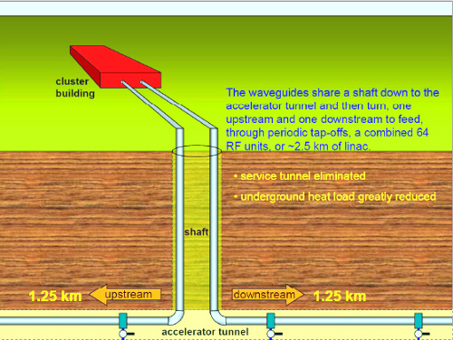 RF klystron cluster configuration with serviceable klystron buildings on the surface RF klystron cluster configuration with serviceable klystron buildings on the surface |
For single-tunnel configurations, two different novel concepts are being pursued for the high-level RF distribution and the choice between them may depend on the actual site characteristics. One approach is to employ a distributed RF system (DRFS). The other is to use a clustered klystron (HLRF) approach. In each case, the total cost is being determined, but we expect both will result in significant cost savings with respect to the double-tunnel RDR configuration.
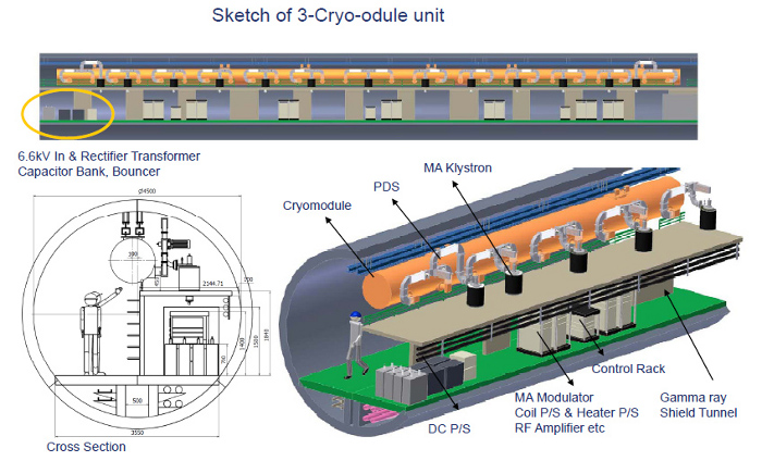
In a little more detail, DRFS consists of about 8000 times 800-kW modulating anode klystrons (MAK), modulators and power supplies installed in the (single) tunnel. In a MAK, a secondary anode near the klystron gun is used, much like a grid in a conventional tube to control the tube beam current. Each MAK drives two cavities (under nominal power specifications from the RDR). With the alternative klystron cluster approach around 35 of the baseline ILC 10-MW multi-beam klystrons (MBK) are located in a surface building and the RF power is combined and transported via a single over-moded waveguide into the underground tunnel, where power is 'tapped off' to drive the cavities. These "clusters" would be located approximately every two kilometres. The associated risks differ in these two schemes.
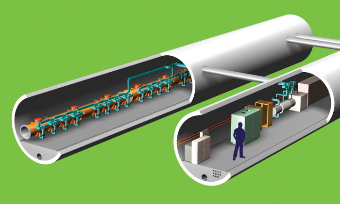
 Tunnel view of a distributed RF concept integrated into a single tunnel main linac Tunnel view of a distributed RF concept integrated into a single tunnel main linac |
The klystron cluster concept requires R&D, now underway at SLAC, to demonstrate the long-pulse power handling of the waveguide components, as well as better understanding of the RF and beam energy control of a one-kilometre-long RF unit. Operational aspects need to be well understood, since a full 'systems test' is not realistic.
KEK is planning to manufacture one DRFS unit in order to show its feasibility on the S1-global test, although we do not expect a problem for a single klystron driving two or four cavities. The main challenge will be in making the concept cost effective, as well as resolving whether a single 4.5-metre diameter tunnel layout is workable or the tunnel diameter must be enlarged.
Finally, I note that today I am giving a snapshot of work in progress. Other options for distributing HLRF for a single tunnel will be considered, including the XFEL two-kilometre linac design, which will provide the most accurate cost estimate. In the upcoming months, we will be studying both HLRF schemes, whether to include both in our TDP-1 baseline and, if so, to develop a realistic subsequent work plan for the Technical Design Phase.
-- Barry Barish